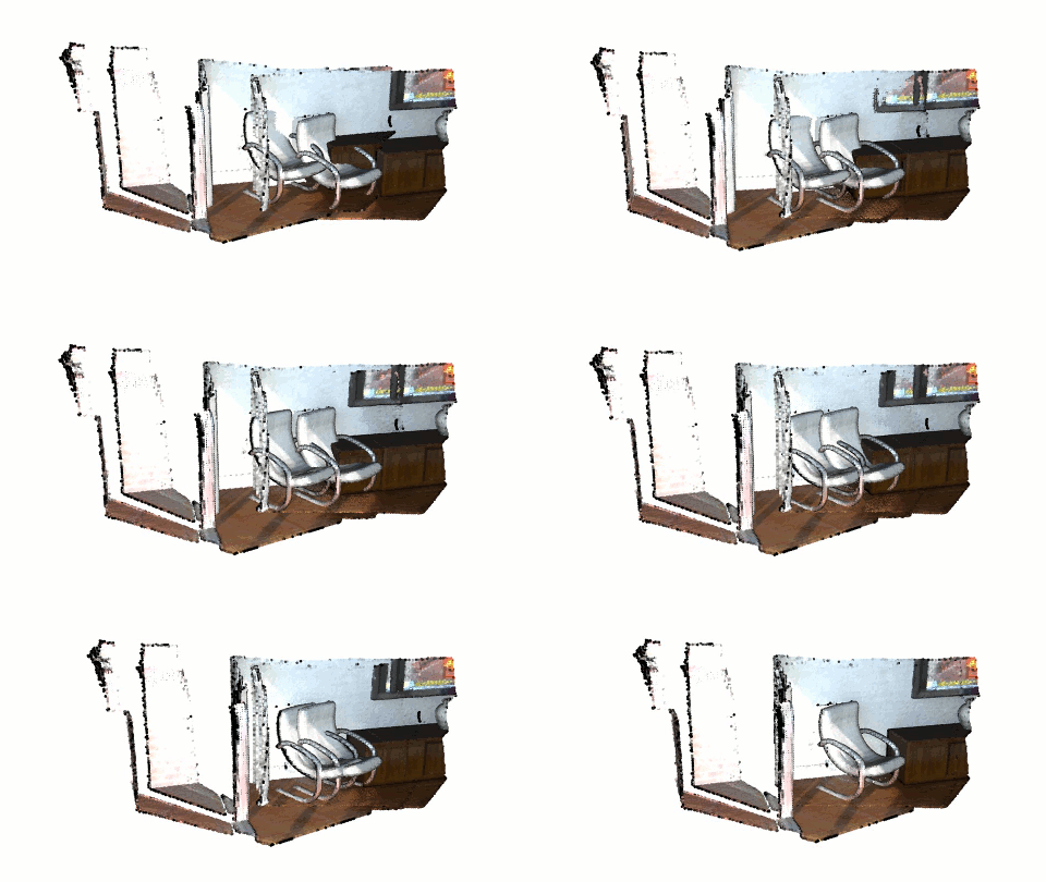
Non-blocking visualization
draw_geometries() is a useful function to get a quick overview of static geometries. However, this function holds a process until a visualization window is closed. This is not optimal when geometry is updated and needs to be visualized without closing the window. This tutorial introduces an example to customize the rendering loop.
Review draw_geometries
draw_geometries has the following rendering-loop (see Visualizer::Run() for the C++ implementation):
while(true):
    if (geometry has changed):
        re-bind geometry to shaders
    if (view parameters have changed):
        re-render the scene
    if (any user mouse/keyboard input):
        respond to it and set flags for re-rendering
Note that both binding geometry and rendering are costly operations, thus they are executed in a lazy way. There are two flags that control them individually. The functions update_geometry and update_renderer set these flags. After rebinding/rendering, these flags are cleared once again.
This rendering loop can be readily customized. For example, a custom loop can be made in this way to visualize ICP registration:
vis = Visualizer()
vis.create_window()
for i in range(icp_iteration):
    # do ICP single iteration
    # transform geometry using ICP
    vis.update_geometry(geometry)
    vis.poll_events()
    vis.update_renderer()
The full script implementing this idea is displayed below.
5 6 7 8 9 10 11 12 13 14 15 16 17 18 19 20 21 22 23 24 25 26 27 28 29 30 31 32 33 34 35 36 37 38 39 40 41 42 43 44 | # examples/python/Advanced/non_blocking_visualization.py
import open3d as o3d
import numpy as np
import copy
if __name__ == "__main__":
o3d.utility.set_verbosity_level(o3d.utility.VerbosityLevel.Debug)
source_raw = o3d.io.read_point_cloud("../../test_data/ICP/cloud_bin_0.pcd")
target_raw = o3d.io.read_point_cloud("../../test_data/ICP/cloud_bin_1.pcd")
source = source_raw.voxel_down_sample(voxel_size=0.02)
target = target_raw.voxel_down_sample(voxel_size=0.02)
trans = [[0.862, 0.011, -0.507, 0.0], [-0.139, 0.967, -0.215, 0.7],
[0.487, 0.255, 0.835, -1.4], [0.0, 0.0, 0.0, 1.0]]
source.transform(trans)
flip_transform = [[1, 0, 0, 0], [0, -1, 0, 0], [0, 0, -1, 0], [0, 0, 0, 1]]
source.transform(flip_transform)
target.transform(flip_transform)
vis = o3d.visualization.Visualizer()
vis.create_window()
vis.add_geometry(source)
vis.add_geometry(target)
threshold = 0.05
icp_iteration = 100
save_image = False
for i in range(icp_iteration):
reg_p2l = o3d.pipelines.registration.registration_icp(
source, target, threshold, np.identity(4),
o3d.pipelines.registration.TransformationEstimationPointToPlane(),
o3d.pipelines.registration.ICPConvergenceCriteria(max_iteration=1))
source.transform(reg_p2l.transformation)
vis.update_geometry(source)
vis.poll_events()
vis.update_renderer()
if save_image:
vis.capture_screen_image("temp_%04d.jpg" % i)
vis.destroy_window()
|
The following sections explain this script.
Prepare example data
13 14 15 16 17 18 19 20 21 22 23 | source_raw = o3d.io.read_point_cloud("../../test_data/ICP/cloud_bin_0.pcd")
target_raw = o3d.io.read_point_cloud("../../test_data/ICP/cloud_bin_1.pcd")
source = source_raw.voxel_down_sample(voxel_size=0.02)
target = target_raw.voxel_down_sample(voxel_size=0.02)
trans = [[0.862, 0.011, -0.507, 0.0], [-0.139, 0.967, -0.215, 0.7],
[0.487, 0.255, 0.835, -1.4], [0.0, 0.0, 0.0, 1.0]]
source.transform(trans)
flip_transform = [[1, 0, 0, 0], [0, -1, 0, 0], [0, 0, -1, 0], [0, 0, 0, 1]]
source.transform(flip_transform)
target.transform(flip_transform)
|
This part reads two point clouds and downsamples them. The source point cloud is intentionally transformed for the misalignment. Both point clouds are flipped for better visualization.
Initialize Visualizer class
25 26 27 28 | vis = o3d.visualization.Visualizer()
vis.create_window()
vis.add_geometry(source)
vis.add_geometry(target)
|
These lines make an instance of the visualizer class, open a visualizer window, and add two geometries to the visualizer.
Transform geometry and visualize it
33 34 35 36 37 38 39 40 41 42 43 44 | for i in range(icp_iteration):
reg_p2l = o3d.pipelines.registration.registration_icp(
source, target, threshold, np.identity(4),
o3d.pipelines.registration.TransformationEstimationPointToPlane(),
o3d.pipelines.registration.ICPConvergenceCriteria(max_iteration=1))
source.transform(reg_p2l.transformation)
vis.update_geometry(source)
vis.poll_events()
vis.update_renderer()
if save_image:
vis.capture_screen_image("temp_%04d.jpg" % i)
vis.destroy_window()
|
This script calls registration_icp for every iteration. Note that it explicitly forces only one ICP iteration via ICPConvergenceCriteria(max_iteration = 1). This is a trick to retrieve a slight pose update from a single ICP iteration. After ICP, source geometry is transformed accordingly.
The next part of the script is the core of this tutorial. update_geometry informs the vis that the related geometries are updated. Finally, the visualizer renders a new frame by calling poll_events and update_renderer. After any for-loop iterations, destroy_window closes the window.
The result looks like the image below.
